
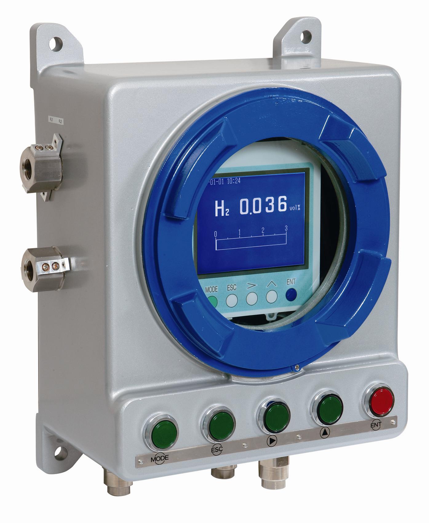
Description
Measuring principle
Optional Specifications
Allowable load resistance
Display unit
Display language
Power supply
Ambient temperature
Mounting
Mass
Housing
Measurable range
Measurable component
Output resistance
Display of measured value
Output signal holding
Warm-up time
Storage conditions
External dimensions(H×W×D)
Finish color
Measurement of thermal conductivity
Standard Gas Measurement Conditions
550Ωmax. (in 4 to 20mA DC output)
LCD with backlight
English
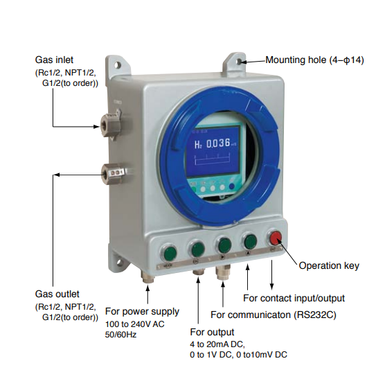
100 to 240V AC, 50/60Hz, Approx. 50VA
-5 to 45℃
Ambient humidity Less than 90% RH (condensation unallowable)
Flush mounting on panel
Approx. 5kg
Steel-plate case, indoor type
As specified for particular type.
Output signal 4 to 20mA DC, 0 to 1V DC, 0 to 10mV DC
Non-isolated output(Any one-output signal specifiable in CODE SYMBOLS)
Material of gascontacting parts
JIS SUS304, platinum, platinum iridium, silver,fluororubber, epoxy resin,
nickel, tin
He,Ar,H2,CH4,CO2
Performance
Repeatability ±1% of F.S.
Drift Zero point:Within ±2% of full scale/week (H2 meter, reference gas N2)
Span:Within ±2% of full scale/week (H2 meter, reference gas N2)
Response speed
(90% response)
Standard within 60sec (at flow rate 0.4L/min)
High speed within 10sec (at flow rate 1L/min), allowed only for H2 meter
(reference gas N2)
100kΩ(in 0 to 1V DC or 0 to 10mV DC output)
Max. 4 digits
In both manual and automatic calibrations, output value just before calibration can be held.
At least 30min
-20~60℃, less than 95% RH (condensation unallowable)
240×192×213mm
Gas inlet/outlet, purge port
Purge gas flow rate
Applied standard
Rc1/4 or NPT1/4 (whichever specified)
Approx. 1L/min (as required)
CE mark (Option)
Off-white (equivalent to 10Y7.5/0.5)
Installation Conditions
Gas flow rate
Pressure
Moisture
Temperature
Dust
Mist,Corrosive gas
Constant at 0.4±0.05 L/min
10kPa max.
Below saturation at 2℃
Standard gases
for calibration
Zero gas: same as reference gas
Span gas: Concentration within 90 to 100% of measuring range
Concentration beyond 100% is inapplicable.
Interference gas
measured value input
Analog input for H2 meter interference correction (1 to 5V DC)
Either CO2 or CH4 component of an external gas analyzer is to be input.
Adjustment is required at Fuji Electric’s factory.
Details of measurement gas will be checked when receiving an order.
Communicating function
RS-232C (9-pin D-sub output)
Half duplex, asynchronous
MODBUSTM protocol, communication speed 9600 bps
Contents of communication: Reading/writing of measured concentration
values and various set values, and output of device status
Automatic calibration
function
Zero and span calibrations are automatically carried out at the predetermined
intervals.
Calibration gases are flowed sequentially by driving the externally installed
solenoid valves.
Contact input
3 non-voltage contact inputs
ON; 0 V, OFF; 5V DC, current at ON; 5mA
Isolated with photo coupler between inputs and internal circuit.
Not isolated between contact inputs.
The following actions can be input.
①Remote holding of measured value output
②Remote range changeover (only with 2-range meter)
③Remote start of automatic calibration
Relay contact output
5 SPST relay contact outputs
Relay contact capacity; 220V AC/2A (resistive load)
Isolated with relay between contacts, and between contacts and internal circuit.
Max. 5 functions are selectable among those listed below.
①Zero-side solenoid valve drive output for automatic calibration
②Span-side solenoid valve drive output for automatic calibration
③Suction pump OFF output in automatic calibration
④Upper limit (1point) concentration alarm output
⑤Lower limit (1point) concentration alarm output
⑥Upper/lower limit (1point) concentration alarm output
⑦Upper limit (1point) and lower limit (1point) concentration alarm output
(Total 2 points)
⑧2-step upper limit (1point at each step) concentration alarm output
(Total 2 points)
⑨2-step lower limit (1point at each step) concentration alarm output
(Total 2 points)
⑩Analyzer error or automatic calibration error alarm output
⑪Calibrating status output
⑫Range identification output (for 2 range type only)
0 to 50℃
Less than 100μg/Nm3 with a particle size of 0.3μm max.
Unallowable
Front view
Panel cutout
(M3.5screw)
(M3.5 screw)
Side view Rear view
Outline Diagram (Standard type) (Unit: mm)
(Unit: mm) Connection Diagram
L
N
E
+
-
Measured value
output (as specified)
4 to 20mA DC
0 to 1V DC
0 to 10mV DC
Power supply
100 to 240V AC,
50/60Hz
Grounding terminal
DO1
DO1
DO2
DO2
DO3
DO3
DO4
DO4
DO5
DO5
AIN+
AIN-
DI1
DI2
DI2
DI3
DI3
DI1
Remote output
holding
Remote range
changeover
Remote automatic
calibration start
Interference correcting
input 1 to 5V DC
・ The analyzer should not be exposed to direct sunlight or radiation from a hot object.
・ A place subjected to heavy vibrations should be avoided. A location with clean
atmosphere should be selected.
・ Before measuring combustible gases, the existing gases should be purged from
the analyzer using air or N2.
・ When the analyzer is installed outdoors, it should be sheltered with a housing or
cover to protect it from rain and wind.
Reviews
There are no reviews yet.